From Idea to CAD to Print, the Exo Pi Case
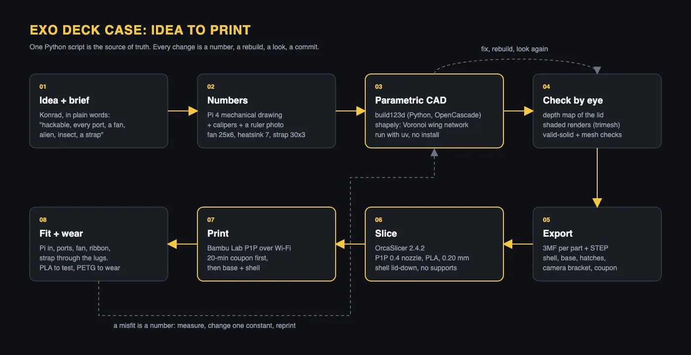
How the Raspberry Pi 4 case for the Exo deck went from a one-paragraph brief to a parametric Python model, with the mistakes along the way, and what gets printed next on our own Bambu Lab P1P. Nothing is printed yet, and this post says so.
The last post showed concept renders of Exo's printed parts. This one is about the first real one: the case for the Raspberry Pi 4 that runs the deck. We took it from a paragraph of intent to a model we can slice, in two days, working with Claude Code. Nothing is printed yet. Everything below is design, measurement and a few mistakes caught before they cost plastic.
The brief
Konrad's brief was short. The case must be hackable: every port reachable, a fan, a way out for the camera ribbon, and room to add sensors later. It should hang from a 30 mm shoulder strap. And it should look like it belongs to Exo, not like a stock plastic box.
Who did what: Konrad gave the brief, the measurements and the photos. Claude Code wrote and iterated the CAD script with him, one change at a time, checking each build before the next.
The tool stack
The case is a Python script, not a file you drag around in a CAD program. That means every dimension is a named constant, and a change to the fan size or the wall thickness is one edit and a rebuild.
| Tool | What it did | Licence |
|---|---|---|
| build123d | Builds the solids in Python on the OpenCascade kernel | Apache-2.0 |
| uv | Runs the script with its dependencies and no install | MIT or Apache-2.0 |
| shapely | Computes the Voronoi network on the lid | BSD-3-Clause |
| trimesh, matplotlib, Pillow | The lid depth map and the shaded renders | MIT; Matplotlib licence (PSF-style); MIT-CMU |
| OrcaSlicer 2.4.2 | Slices the 3MF files for the printer | Open source, AGPL-3.0 |
| Bambu Lab P1P | Prints them: 0.4 mm nozzle, no AMS | Hardware |
The whole build is one line at the top of the script:
uv run --no-project --with build123d --with shapely --with numpy python pi4_deck_case.py
First model, from a drawing
The first version came from the Raspberry Pi 4 mechanical drawing: a 85 x 56 mm board, four M2.5 holes, the port positions along the HDMI edge, the GPIO header, the camera connector. The script's coordinates start at the SD-card end and the HDMI edge, so every feature is a distance from a corner you can find on the real board.
The numbers it could not get from a drawing are marked MEASURE in the script, to be checked with calipers before any full print. That list turned out to matter.
Branding and the strap
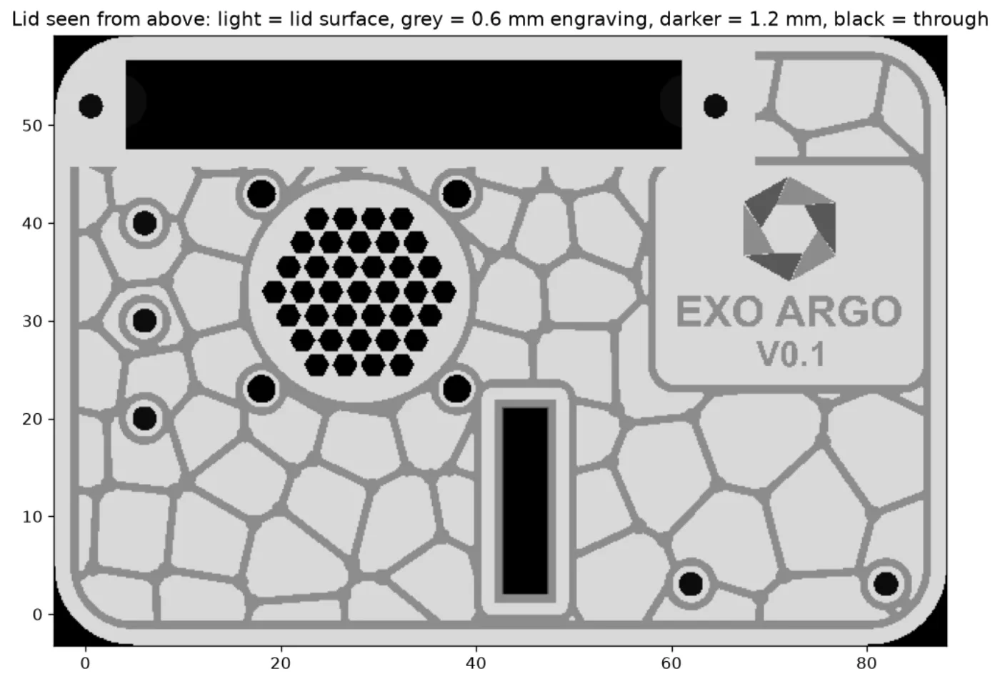
Next came the identity. The lid carries the Argo emblem, traced from the logo file into three light and three dark facets (0.6 mm and 1.2 mm deep), then "EXO ARGO" with "V0.1" under it, and the URL exo.myargoquest.com. The strap, a 30 mm webbing, first got a screw-on plate, then a better idea: it feeds through the case itself. The base became a full-footprint plate with two strap lugs, 121.4 mm long with the lugs, and a 1.0 mm rim that locates the shell.
v1: the alien carapace
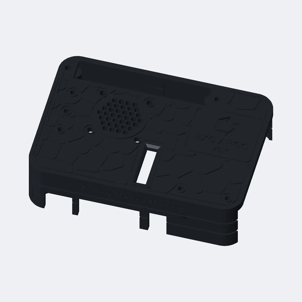
Konrad's next brief was "rounded, polished, alien, an extension of the body". The model answered with walls tapered 5 degrees, a chamfered lid, grooves round the walls, a honeycomb fan grille and five engraved veins.
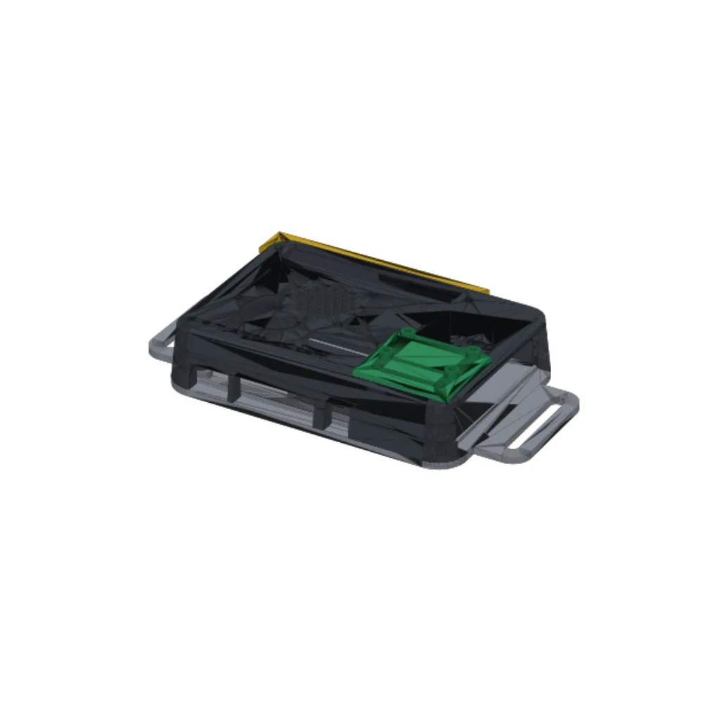
Konrad rejected it. The walls should be square to the front and back, with only the corners rounded. And it should read more as insect, sci-fi, network: a spaceship or an alien object from the future, not a smooth pebble.
v2: straight walls and a wing network
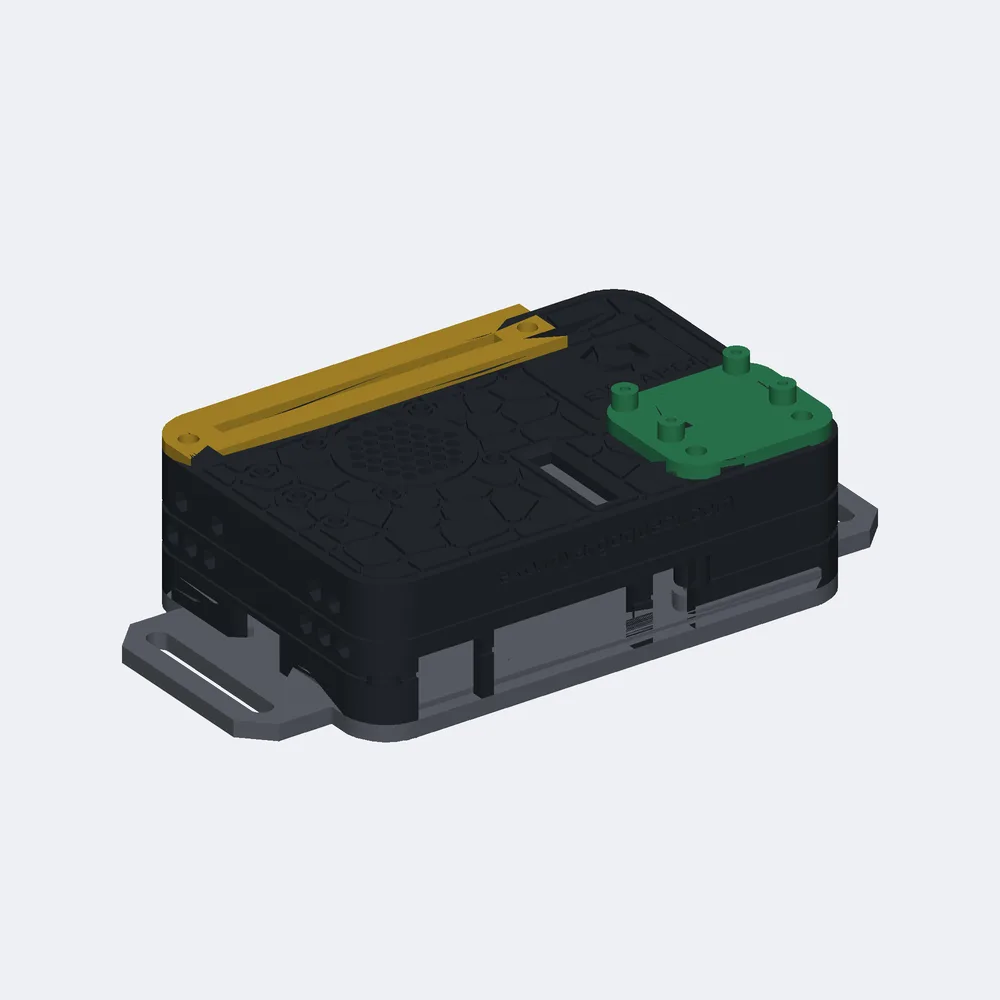
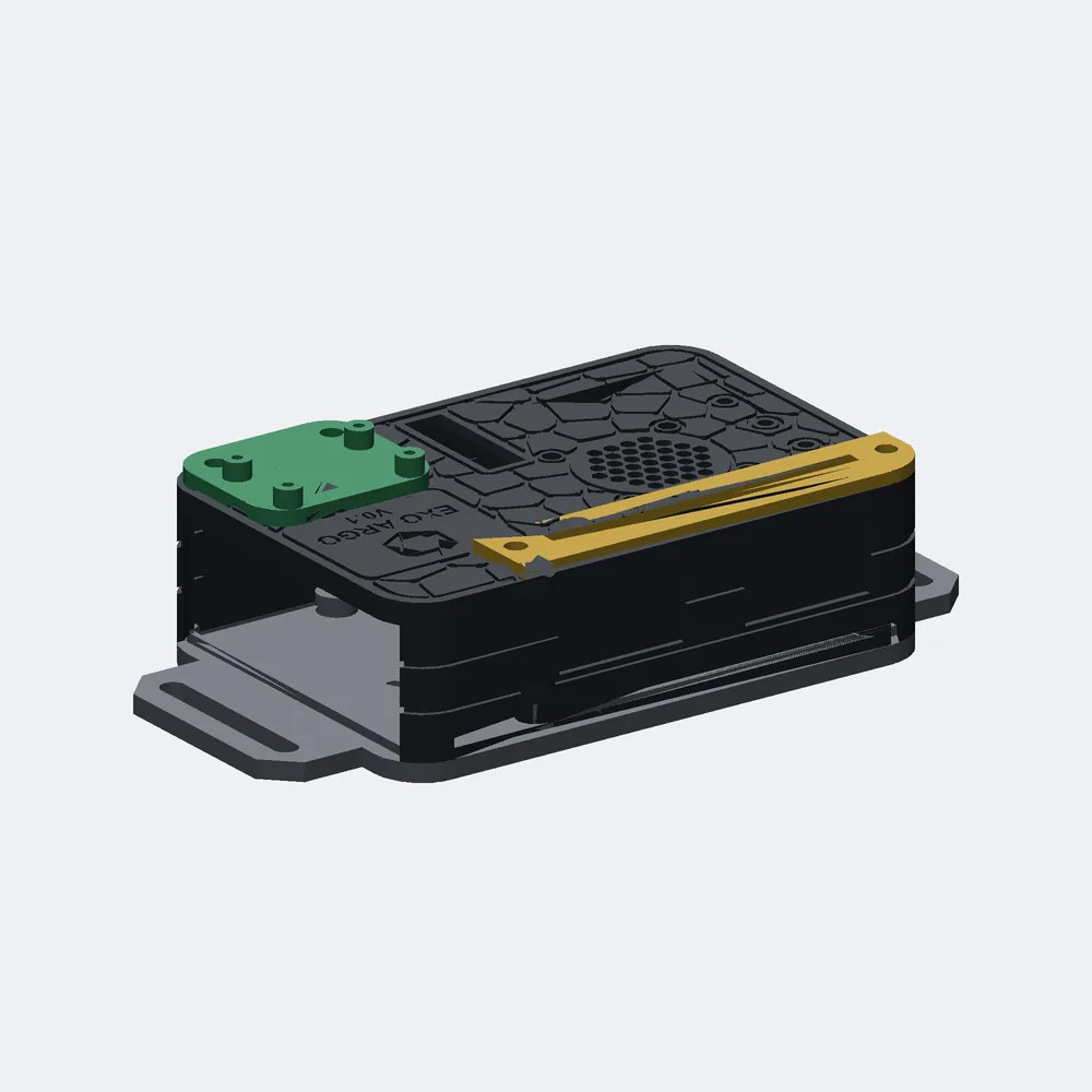
The redesign changed the body into one straight extrusion with 8 mm corner radii. The base has the same footprint, so shell and base sit flush at 91.4 x 62.4 x 27.5 mm.
The "dragonfly wing" on the lid is a Voronoi network. shapely seeds cells with a 12-point rosette around the fan, then adds more seeds whose spacing grows with distance from the fan, so the cells are small near the fan and large at the edges. The cell borders become 0.8 mm wide, 0.6 mm deep grooves (two nozzle widths, three layers), with a small node at every three-way junction and rings round every hole. The fan grille became a compound eye of hexagon cells, and the SD-card end got ten point-up hexagonal vents, which print without supports. The strap lugs got faceted noses instead of round ones.
The mistakes
Four of them are worth telling, because each was caught by looking at the model, not by wasting a print.
- The engraving vanished. The first v2 build had no network on the lid. shapely returned its polygons wound clockwise, so the faces pointed down and the cut went into the lid's inside instead of its top. The same bug put one strap lug 3 mm below the bed, which showed up as a base reporting 9.0 mm tall instead of 6.0. We caught it on the lid depth map and fixed it by forcing the winding.
- The base rim would have hit the wall. The rim's square corner reached about 0.8 mm into the shell's rounded wall. A fit bug from the first model, found when the rim was rounded to match.
- The camera slot was turned 90 degrees. This one is Konrad's catch. He looked at the hero render, saw the slot running parallel to the HDMI edge, and checked his own board. The camera connector runs across it.
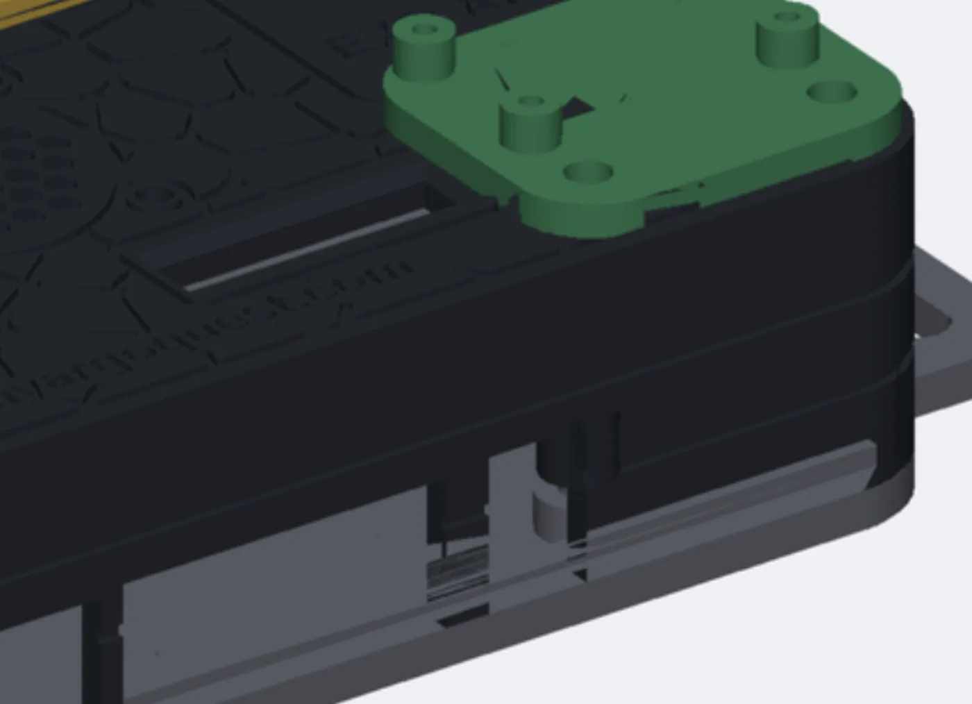
The slot was 22 mm along the board and 4.5 mm across it, so the 16 mm ribbon would have had to twist 90 degrees right above the connector. It is now 4.5 mm along and 19 mm across: not the connector's 22, because the ribbon is 16 mm wide and 19 mm keeps 1.8 mm of lid between the lead-in and the edge. - The coupon tested the wrong screw hole. The 20-minute fit test is meant to prove that an M2.5 screw cuts its thread in the shell's posts. Its post first got the base's 2.8 mm clearance hole, where a screw just slides through, so it tested nothing. It now has the shell posts' 2.2 mm pilot, 6 mm deep. A test that checks the wrong thing is worse than no test.
Two of these were a modelling error from a clockwise polygon and a rotation. Neither was a design decision. That is the case for rendering every change and reading the render.
Measuring the real board
A photo is also a measurement tool. Konrad shot his Pi 4 with a ruler beside it, zero at the SD-card end.
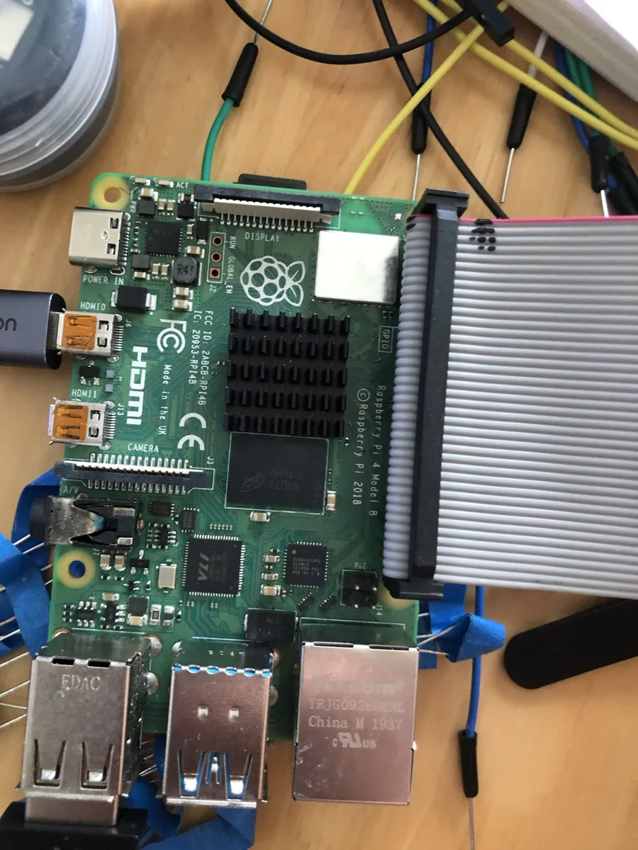
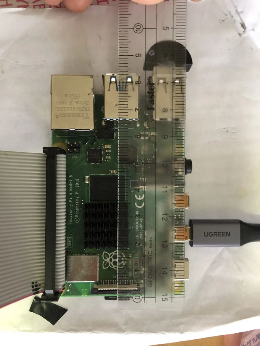
From the photos we read off positions. The camera connector's centre is about 44 mm from the SD end and about 11 mm from the HDMI edge, matching the model. The finned heatsink on the processor is about 17 x 17 mm, centred about 27 to 28 mm from the SD end and 33 mm from the HDMI edge, so the script now puts the fan over (28, 33) mm. The photo scale was about 12.5 px per mm, checked against the 13 mm USB 3 jack and the 16 mm Ethernet jack. These are photo estimates, not caliper readings.
Konrad measured the rest by hand: fan 25 x 6 mm, heatsink 7 mm above the board, USB-C plug body 10 x 6 mm, strap 30 x 3 mm, fan screws M2.5. A fan, a heatsink and a lid have to share a few millimetres. With the inside of the lid 17.1 mm above the board, the fan (6 mm) on top of the heatsink (7 mm) leaves 4.1 mm of clearance, and the design wants about 1 mm. Had the heatsink been taller, the lid would have had to go up.
The photo of the board also showed the grey 40-pin ribbon already on the GPIO header, which decides which of the three hatch plates gets printed first: the fully open one.
The camera pin
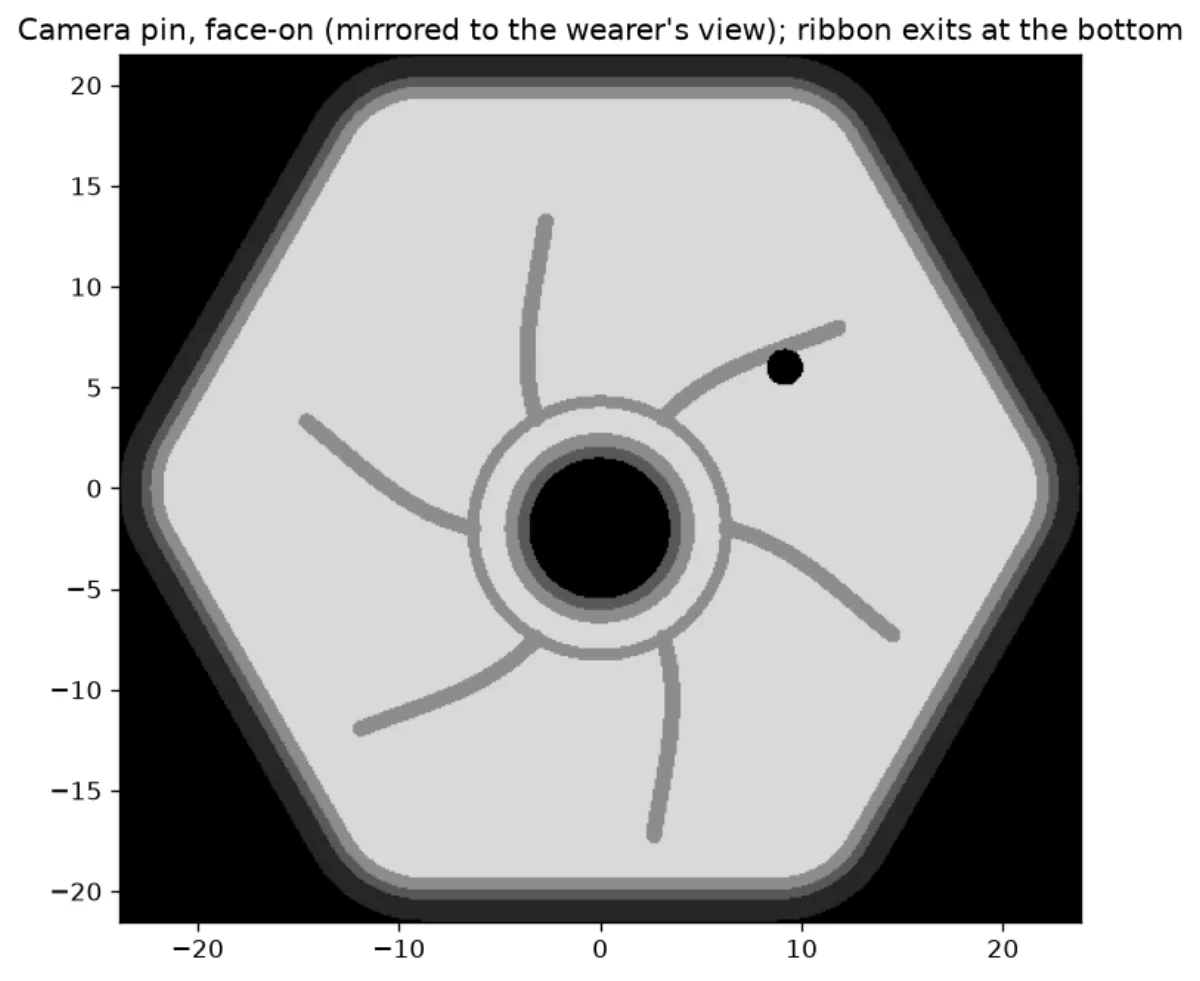
The camera has its own part: a hexagonal pin for the Pi Camera Rev 1.3, 47.8 x 43.0 x 13.5 mm, with an iris, swirl veins, an LED window and a shelf and clamp bar for the ribbon. It still has 6 degree walls from the v1 look. Whether it should go straight too is an open question.
The print
Nothing is printed yet. This is the plan, in order:
Everything prints on the Bambu Lab P1P (0.4 mm nozzle, no AMS), sliced in OrcaSlicer 2.4.2 with Konrad's saved presets: "0.20mm Standard @BBL P1P - slow" for the process, which has a slower first layer, and "Bambu PLA Basic @BBL P1P" for the filament. Supports are off for every part.
- The coupon, in PLA. A 40 x 20 x 14 mm piece, estimated at about 20 minutes, laid flat as exported. Settings: 3 wall loops, 15% sparse infill, elephant-foot compensation 0.15 mm. It holds four things to check: - Shell post. An M2.5 screw cuts its thread into the 2.2 mm pilot and holds. This is what will clamp the Pi. - USB-C notch. The 10 x 6 mm power plug drops in with about 1 mm to spare. - M3 grid hole. An M3 screw self-taps in and grips. - M2 camera boss. An M2 screw self-taps in.
- The base, then the shell, in PLA. The base prints floor down, estimated at about 1.5 hours. The shell prints upside down, lid on the bed with the walls standing up, estimated at about 3 hours. Printing the lid against the plate keeps the wing network and the emblem crisp, and the plate's texture ends up on the lid: glossy on a smooth plate, matte on textured PEI. The test fit checks that the Pi sits on the standoffs, the shell lowers over the connectors without force, and every plug goes in.
- The hatch and the camera bracket. The open hatch plate (about 10 minutes) and the camera bracket (about 15 minutes), both flat.
- The worn case, in PETG. PLA softens at about 57 degrees C and the Pi 4 runs warm, so the case that goes on a body is reprinted in PETG once the fit is right. PETG shrinks a little differently, so that fit gets checked again.
The times are the guide's estimates. OrcaSlicer shows the real ones after slicing, and we have none yet. Photos of the finished case will be added to this post after the print.
The model is hardware/case/pi4_deck_case.py in the argo-exo repo.